
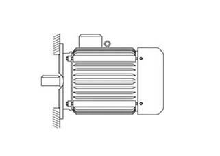
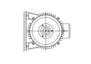
Installation B5
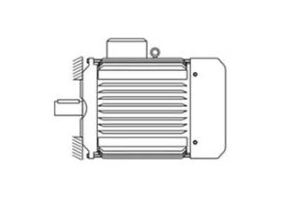
Installation B14
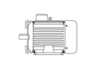
Installation B34
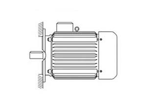
Installation B35
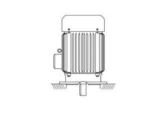
Installation V1
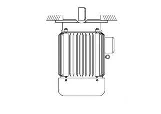
Installation V3
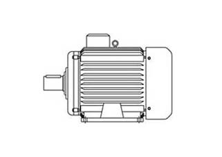
Installation B3
Installation B6
Installation B7
Installation B8
“Vikrant” motors up to 3kw normally designed for star connection for 415V, 50Hz, 3 Phase supply, but with increasing usage of 230V inverter, these motors are supplied with six terminals to create star or delta connection as required. Motors above 4kw are normally supplied with six terminals for star-delta connections. Motors with six terminals have to be connected in accordance with supply conditions. Verify the connection instruction before putting the motor in operation. With different connections of the motor, it is possible to use the same motor of different voltage supplies (Dual voltage motor).
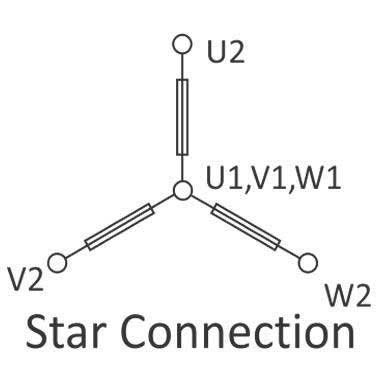
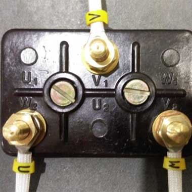
On a six termination plate, connect U1, V1 and W1 with the link supplied along with the motor and connect three-phase supply wires to U2 , V2 and W2 to connect the motor in star connection.
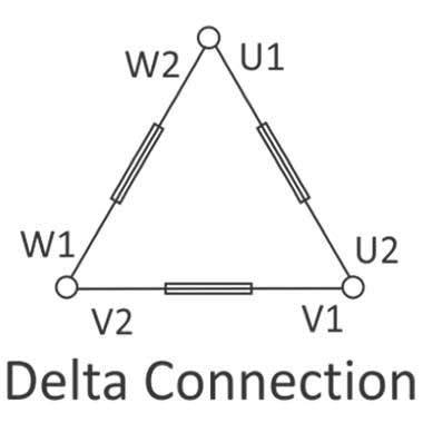
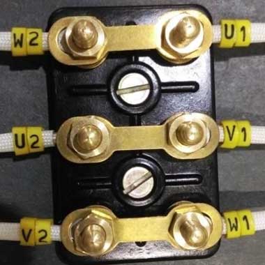
On a Six termination plate, connect V1-U2, U1-W2 and W1-V2 with the link supplied along with the motor and connect three-phase supply wires to U1, V1 and W1 to connect the motor in delta connection.
While changing the connections, ensure that the rated Voltage is maintained on the supply to brake, rectifier or any other type of accessories / equipment which are directly connected to the motor termination.
| kW/HP | Average Current | Fuse Rating | Relay Range |
|---|---|---|---|
| 0.37/0.5 | 1.1 | 4 | 1-2 |
| 0.55/0.75 | 1.4 | 6 | 1.2 |
| 0.75/1.0 | 1.9 | 6 | 1.2 |
| 1.1/1.5 | 2.6 | 6 | 2-4 |
| 1.5/2.0 | 3.7 | 10 | 2-4 |
| 2.2/3.0 | 4.8 | 16 | 3-6 |
| 3.7/5.0 | 7.8 | 16 | 6-12 |
| 5.5/7.5 | 11.2 | 25 | 6-12 |
| 7.5/10 | 15 | 25 | 10-16 |
| 9.3/12.5 | 18 | 35 | 18-24 |
| 11/15 | 21 | 35 | 18-24 |
| 15/20 | 27 | 50 | 16-32 |
| 18.5/25 | 33 | 63 | 24-45 |
| 22/30 | 39 | 63 | 24-45 |
| 30/40 | 53 | 100 | 32-63 |
| 37/50 | 65 | 100 | 50-90 |
| 45/60 | 78 | 160 | 50-90 |
| kW/HP | Line | Average Current | Relay Range | |
|---|---|---|---|---|
| Phase | Fuse Rating | |||
| 3.7/5.0 | 7.8 | 4.5 | 16 | 1.5-3 |
| 5.5/7.5 | 11.2 | 6.5 | 25 | 4-8 |
| 7.5/10 | 15 | 9 | 25 | 6-12 |
| 9.3/12.5 | 18 | 11 | 35 | 6-12 |
| 11/15 | 21 | 12.7 | 35 | 10-16 |
| 15/20 | 27 | 16.8 | 50 | 18-24 |
| 18.5/25 | 33 | 20.2 | 63 | 18-24 |
| 22/30 | 39 | 23.2 | 63 | 18-24 |
| 30/40 | 53 | 30.6 | 100 | 16-32 |
| 37/50 | 65 | 37.5 | 100 | 24-45 |
| 45/60 | 78 | 46.4 | 160 | 32-50 |
| 55/75 | 92 | 53.2 | 200 | 50-63 |
If you keep in your mind all these important things then you can save your electricity as well as maintenance charge.

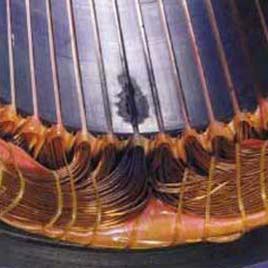
Winding Shorted
Turn-To-Turn
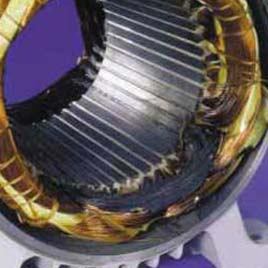
Winding With Shorted Coil
Winding Grounded
at Edge of Slot
Winding Grounded at the Slot
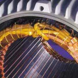
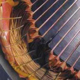
Shorted Connection
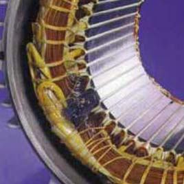
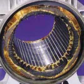
Winding Damage
Due To Overload
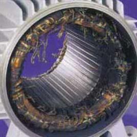
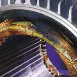
Damage Caused
By Locked Rotor
Winding Damaged
By Voltage Surge
Winding Shorted
Phased-To-Phased
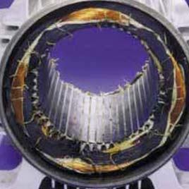
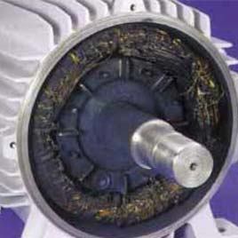
Winding Single Phased
(Y-Connected)
Winding Single Phased
(A-Connected)
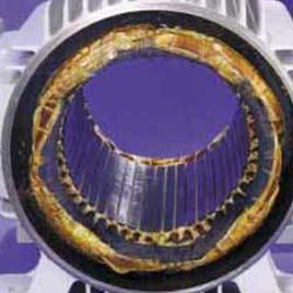
Phase Damaged Due to Unbalanced Supply Voltage